Layer-2 VPNs on Junos
Table of Contents
It has been a busy few weeks trying to stay ahead of all the new work that has been coming towards myself and the team, due to the in sourcing of the core network! Lucky enough for my team, we have finally got our hands onto full end-to-end connectivity! Fun times :D
With that being said, I’ve been given a wee project to provision a circuit for a business customer between two sites for a Proof Of Concept. As this circuit is being using as a POC (for now), it was agreed that a Layer 2 VPN (L2VPN/pseudowire) will be best suited, because a simple point-to-point connection was needed between two PEs. As we have a MPLS enabled network, it was decided that would be the easiest way to get their POC up and running quickly, as we were under a bit of a hard deadline!
For me, it was good little project, even though I know what L2VPNs were and how they work, I had never configured one myself. You see where I’m going with this now?
This post will over note how to configure L2VPN with Junos :D
L2VPN, also known as a pseudowire, is defined in RFC4665, where they are called Virtual Private Wire Service (VPWS):
The PE devices provide a logical interconnect such that a pair of CE devices appears to be connected by a single logical Layer 2 circuit. PE devices act as Layer 2 circuit switches. Layer 2 circuits are then mapped onto tunnels in the SP network. These tunnels can either be specific to a particular VPWS, or be shared among several services. VPWS applies for all services, including Ethernet, ATM, Frame Relay, etc. Each PE device is responsible for allocating customer Layer 2 frames to the appropriate VPWS and for proper forwarding to the intended destinations.
In essence, L2VPNs are virtual point-to-point circuit that use the underlying Transport Labels (LDP/RSVP) or a statically defined MPLS path to go between two PE’s, that allows the extension of a layer 2 broadcast domain. If you need multiple sites on the same layer 2 broadcast you will need to consider Virtual Private Lan Service (VPLS) or Ethernet VPN (EVPN).
Within Junos there are 3 ways of configuring L2VPNs, two are regarded as modern way and has been rectified with RFC’s with an additional legacy method. Kompella and Martini are regarded as the industry standard, with Circuit Cross-Connect (CCC) seen as legacy:
Circuit Cross-Connect: The Circuit Cross-Connect style of L2VPN uses a single Outer Label, also known as the Tunnel/Transport Label, to transport L2 payload from PE to PE. CCC can ONLY use RSVP as MPLS transport, in addition each CCC connection has its own dedicated RSVP-signalled LSP associated, the transport label cannot be shared between multiple connections. LSPs are manually created on each PE to determines which circuit the frame belongs to on the other end.Martini: The Martini style of L2VPN has a pair of labels before the L2 frame. The Outer label is the transport mechanism that allows the frame from egress interface from the sending PE to ingress interface of the receiving PE. The Inner label, known as the VC Label, is the label that informs the receiving PE, where the L2VPN payload should go. It is important to note that if you are using the Martini style, although either LDP or RVSP can be used MPLS transport, that LDP is used for the signalling of the VC label. So if the RSVP is used as the MPLS transport, LDP will need to be enabled on the loopback address of both PE routers. A minimum of 2 LSPs will need to be set, as MPLS LSPs are unidirectional.Kompella: The Kompella style of L2VPN is similar to Martini style as both use stacked labels before the Layer 2 payload and both can use LDP, RSVP or both as Transport Label. There difference comes in that unlike Martini, Kompella uses BGP signalling as its VC Label. This means you will need to have BGP enabled network, in addition, it’s not compulsory to send static LSPs as BGP provides a mechanism for autodiscovery of new point-to-point links similar to a VPLS. Although Kompella has a more complex configuration, because of its usage of BGP signalling it is regarded as the best option for large scale deployments as it will in-conjunction with other BGP families. RFC6624 has more details on L2VPN using BGP for Auto-Discovery and Signaling
In our network, we use the Kompella style of L2VPNs. The bulk and most depth of my testing was with that method… Although I was able to get a wee bit of naughty time after to configure the other methods :)
The topology I’ll be working with is a simple one. I’ve a got a single MX480 broken up into 3 Logical Systems.
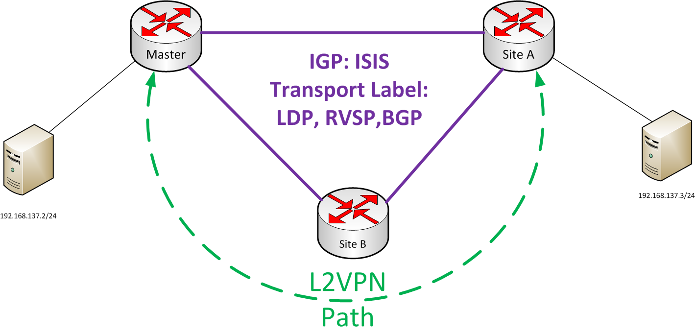
The underlying IGP is IS-IS with RSVP, LDP and BGP enabled. This is a mirror, of what we have in production. With all the L2VPNs the customer facing physical interface has to be set to the correct encapsulation. For my testing, as I wont be using VLANs, Bridging or Setting a VPLS. I used ethernet-ccc and had set the logical interface to family ccc, you can find out more about the different physical encapsulations here
Base Configuration⌗
set interfaces xe-0/1/0 enable
set interfaces xe-0/1/0 encapsulation ethernet-ccc
set interfaces xe-0/1/0 unit 0 family ccc
set protocols rsvp interface xe-1/0/0.0
set protocols rsvp interface xe-1/0/2.0
set protocols mpls explicit-null
set protocols mpls ipv6-tunneling
set protocols mpls no-decrement-ttl
set protocols mpls interface xe-1/0/0.0
set protocols mpls interface xe-1/0/2.0
set protocols bgp group Master type internal
set protocols bgp group Master local-address 192.168.2.1
set protocols bgp group Master family inet unicast
set protocols bgp group Master family inet6 unicast
set protocols bgp group Master local-as 100
set protocols bgp group Master neighbor 192.168.2.2
set protocols bgp group Master neighbor 192.168.2.3
set protocols isis reference-bandwidth 1000g
set protocols isis level 1 disable
set protocols isis level 2 wide-metrics-only
set protocols isis interface xe-1/0/0.0 ldp-synchronization
set protocols isis interface xe-1/0/0.0 point-to-point
set protocols isis interface xe-1/0/0.0 link-protection
set protocols isis interface xe-1/0/2.0 ldp-synchronization
set protocols isis interface xe-1/0/2.0 point-to-point
set protocols isis interface xe-1/0/2.0 link-protection
set protocols isis interface xe-1/0/3.0 ldp-synchronization
set protocols isis interface xe-1/0/3.0 point-to-point
set protocols isis interface xe-1/0/3.0 link-protection
set protocols isis interface lo0.0
set protocols ldp track-igp-metric
set protocols ldp explicit-null
set protocols ldp transport-address router-id
set protocols ldp interface xe-1/0/0.0
set protocols ldp interface xe-1/0/2.0
set protocols ldp interface lo0.0
All configurations will be done on the Master and SiteA, and for my examples I will show work done on the Master Instance. With all that out of the way… Let’s get cracking :D
Kompella⌗
As stated before, BGP is used as the VPN signalling method, with that in mind, we will need to enable layer-2 signalling within MP-BGP. This is simply done by adding the command family l2vpn signaling with the BGP stanza. This can be added globally within BGP or under the specific neighbour.
set protocols bgp group Master family l2vpn signaling
With the signalling sorted we can go straight into the configuration of the L2VPN. Just like L3VPNs, L2VPNs configuration is done within the routing-instance stanza and uses the same parameters as L3VPN by having Route Distinguisher (RD) and Route-Target/vrf-target (RT). The RD has to be unique per device with RT matching on all devices within the L2VPN, this is important, so that traffic can be routed accordingly per site. In addition, routing-instance has to be set to l2vpn and the interface(s) have to be defined within the routing-instance as well.
set routing-instances Master instance-type l2vpn
set routing-instances Master interface xe-0/1/0.0
set routing-instances Master route-distinguisher 100:0001
set routing-instances Master vrf-target target:100:0000
Next the properties for that site within the L2VPN will need to configured under protocol l2vpn within the routing-instance. The encapsulation has to match all site that want to participate within the VPN. The Site identifier must be unique to the entire site within the L2VPN as the site ID is used to compute label values for site-to-site communications. The interface(s) have to be defined within l2vpn and l2vpn site stanzas.
set routing-instances Master protocols l2vpn encapsulation-type ethernet
set routing-instances Master protocols l2vpn interface xe-0/1/0.0
set routing-instances Master protocols l2vpn site Master site-identifier 1
set routing-instances Master protocols l2vpn site Master interface xe-0/1/0.0
Full Kompella Configuration⌗
set routing-instances Master instance-type l2vpn
set routing-instances Master interface xe-0/1/0.0
set routing-instances Master route-distinguisher 100:0001
set routing-instances Master vrf-target target:100:0000
set routing-instances Master protocols l2vpn encapsulation-type ethernet
set routing-instances Master protocols l2vpn interface xe-0/1/0.0
set routing-instances Master protocols l2vpn site Master site-identifier 1
set routing-instances Master protocols l2vpn site Master interface xe-0/1/0.0
set protocols bgp group Master family l2vpn signaling
Verification⌗
The primary command that will be used to check the status of a pseudowire would be show l2vpn connections. As Komplella signalling uses BGP, we will be able to do a show bgp summary and see a route being advertised within the l2vpn and routing instance tables show route table Master.l2vpn.0 or show route table bgp.l2vpn.0 respectfully. Additionally we will be able to mpls.0 table to confirm that the L2VPN incoming label and interface(s) for the pseudowire have made the routing table, by using show route table mpls.0.
Show l2vpn Connections⌗
marquk01@TestMX480> show l2vpn connections
Layer-2 VPN connections:

Legend for connection status (St)
EI -- encapsulation invalid      NC -- interface encapsulation not CCC/TCC/VPLS
EM -- encapsulation mismatch     WE -- interface and instance encaps not same
VC-Dn -- Virtual circuit down    NP -- interface hardware not present
CM -- control-word mismatch      -> -- only outbound connection is up
CN -- circuit not provisioned    <- -- only inbound connection is up
OR -- out of range               Up -- operational
OL -- no outgoing label          Dn -- down
LD -- local site signaled down   CF -- call admission control failure
RD -- remote site signaled down  SC -- local and remote site ID collision
LN -- local site not designated  LM -- local site ID not minimum designated
RN -- remote site not designated RM -- remote site ID not minimum designated
XX -- unknown connection status  IL -- no incoming label
MM -- MTU mismatch               MI -- Mesh-Group ID not available
BK -- Backup connection	         ST -- Standby connection
PF -- Profile parse failure      PB -- Profile busy
RS -- remote site standby	 SN -- Static Neighbor
LB -- Local site not best-site   RB -- Remote site not best-site
VM -- VLAN ID mismatch

Legend for interface status
Up -- operational
Dn -- down

Instance: Master
  Local site: Master (1)
    connection-site           Type  St     Time last up          # Up trans
    2                         rmt   Up     Jun  4 12:36:46 2016           2
      Remote PE: 192.168.2.2, Negotiated control-word: Yes (Null)
      Incoming label: 800001, Outgoing label: 800000
      Local interface: xe-0/1/0.0, Status: Up, Encapsulation: ETHERNET
Show bgp summary⌗
marquk01@TestMX480> show bgp summary
Groups: 1 Peers: 2 Down peers: 0
Table          Tot Paths  Act Paths Suppressed    History Damp State    Pending
inet.0
                       0          0          0          0          0          0
inet6.0
                       0          0          0          0          0          0
bgp.l2vpn.0
                       1          1          0          0          0          0
Peer                     AS      InPkt     OutPkt    OutQ   Flaps Last Up/Dwn State|#Active/Received/Accepted/Damped...
192.168.2.2             100       3234       3229       0       1  1d 0:19:17 Establ
  inet.0: 0/0/0/0
  inet6.0: 0/0/0/0
  Master.l2vpn.0: 1/1/1/0
  bgp.l2vpn.0: 1/1/1/0
192.168.2.3             100       5735       5724       0       1 1d 19:06:59 Establ
  inet.0: 0/0/0/0
  inet6.0: 0/0/0/0
  Master.l2vpn.0: 0/0/0/0
  bgp.l2vpn.0: 0/0/0/0/
Show route table Master.l2vpn.0⌗
marquk01@TestMX480> show route table Master.l2vpn.0

Master.l2vpn.0: 2 destinations, 2 routes (2 active, 0 holddown, 0 hidden)
+ = Active Route, - = Last Active, \* = Both

100:1:1:1/96
                   \*\[L2VPN/170/-101\] 1d 20:37:12, metric2 1
                      Indirect
100:2:2:1/96
                   \*\[BGP/170\] 00:01:02, localpref 100, from 192.168.2.2
                      AS path: I, validation-state: unverified
                    > to 192.168.1.14 via xe-1/0/0.0, Push 0
                      to 192.168.1.6 via xe-1/0/2.0, Push 300000
show route table mpls.0⌗
marquk01@TestMX480> show route table mpls.0 protocol l2vpn

mpls.0: 10 destinations, 10 routes (10 active, 0 holddown, 0 hidden)
+ = Active Route, - = Last Active, \* = Both

800001             \*\[L2VPN/7\] 23:30:09
                    > via xe-0/1/0.0, Pop       Offset: 4
xe-0/1/0.0         \*\[L2VPN/7\] 00:06:20, metric2 100
                    > to 192.168.1.14 via xe-1/0/0.0, Push 800000 Offset: 252
                      to 192.168.1.6 via xe-1/0/2.0, Push 800000, Push 300000(top) Offset: 252
From the end host point of view, we have end-to-end connectivity :D
marquk01@km-vm2:~$ ping -c 2 -q 192.168.137.3
PING 192.168.137.3 (192.168.137.3) 56(84) bytes of data.

--- 192.168.137.3 ping statistics ---
2 packets transmitted, 2 received, 0% packet loss, time 1000ms
rtt min/avg/max/mdev = 0.431/0.637/0.843/0.206 ms
The route given from
show route table Master.l2vpn.0is the Route Distinguisher of the other end of the pseudowire
Martini⌗
Martini signalling uses LDP, as stated before, and with LDP enabled already, I will focus on the actual configuration, which is done within the protocol l2circuit stanza. Compared to Kompella, the configuration for Martini style of L2VPNs is much simpler. All that is needed is for:
- The remote neighbour to be defined. In my example I will be using the loopback address SiteA as the remote neighbour
- The customer facing interface connecting into the VPN
- Set a circuit ID, that must match on both sides
All this can be done in one line!
set protocols l2circuit neighbor 192.168.2.2 interface xe-0/1/0.0 virtual-circuit-id 1
With that we have Martini style L2VPN configured :)
Verifications⌗
To check the status of Martini style L2VPN, you will use show l2circuit connections, the output is near enough the same as show l2vpn connections. Martini, as discussed above, uses LDP for the signalling, we will be able to use show ldp neighbor to check that the neighbour relationship with the remote side has been successful and we will be able to check the LDP database by using show ldp database to verify that new labels associated with the pseudowire (L2CKT) has been installed into the database. Additionally you can check the inet.3 and mpls.0 routing tables, by using show route table inet.3 & show route table mpls.0
Show l2circuit Connections⌗
marquk01@TestMX480> show l2circuit connections
Layer-2 Circuit Connections:

Legend for connection status (St)
EI -- encapsulation invalid      NP -- interface h/w not present
MM -- mtu mismatch               Dn -- down
EM -- encapsulation mismatch     VC-Dn -- Virtual circuit Down
CM -- control-word mismatch      Up -- operational
VM -- vlan id mismatch		 CF -- Call admission control failure
OL -- no outgoing label          IB -- TDM incompatible bitrate
NC -- intf encaps not CCC/TCC    TM -- TDM misconfiguration
BK -- Backup Connection          ST -- Standby Connection
CB -- rcvd cell-bundle size bad  SP -- Static Pseudowire
LD -- local site signaled down   RS -- remote site standby
RD -- remote site signaled down  HS -- Hot-standby Connection
XX -- unknown

Legend for interface status
Up -- operational
Dn -- down
Neighbor: 192.168.2.2
    Interface                 Type  St     Time last up          # Up trans
    xe-0/1/0.0(vc 1)          rmt   Up     Jun  5 14:03:37 2016           1
      Remote PE: 192.168.2.2, Negotiated control-word: Yes (Null)
      Incoming label: 300000, Outgoing label: 300016
      Negotiated PW status TLV: No
      Local interface: xe-0/1/0.0, Status: Up, Encapsulation: ETHERNET
      Flow Label Transmit: No, Flow Label Receive: No
Show ldp neighbor⌗
marquk01@TestMX480> show ldp neighbor
Address            Interface          Label space ID         Hold time
192.168.2.2        lo0.0              192.168.2.2:0            43
192.168.1.6        xe-1/0/2.0         192.168.2.3:0            14
192.168.1.14       xe-1/0/0.0         192.168.2.2:0            13
Show ldp database⌗
marquk01@TestMX480> show ldp database
Input label database, 192.168.2.1:0--192.168.2.2:0
  Label     Prefix
 299984      192.168.2.1/32
      0      192.168.2.2/32
 300000      192.168.2.3/32
 300016      L2CKT CtrlWord ETHERNET VC 1

Output label database, 192.168.2.1:0--192.168.2.2:0
  Label     Prefix
      0      192.168.2.1/32
 299968      192.168.2.2/32
 299984      192.168.2.3/32
 300000      L2CKT CtrlWord ETHERNET VC 1

Input label database, 192.168.2.1:0--192.168.2.3:0
  Label     Prefix
 300016      192.168.2.1/32
 300000      192.168.2.2/32
      0      192.168.2.3/32

Output label database, 192.168.2.1:0--192.168.2.3:0
  Label     Prefix
      0      192.168.2.1/32
 299968      192.168.2.2/32
 299984      192.168.2.3/32
Show route table inet.3⌗
marquk01@TestMX480> show route table inet.3 192.168.2.2

inet.3: 3 destinations, 4 routes (3 active, 0 holddown, 0 hidden)
+ = Active Route, - = Last Active, \* = Both

192.168.2.2/32     \*\[LDP/9\] 1d 21:16:06, metric 100
                    > to 192.168.1.14 via xe-1/0/0.0, Push 0
                      to 192.168.1.6 via xe-1/0/2.0, Push 300000
                    \[RSVP/10/1\] 1d 01:14:11, metric 100
                    > to 192.168.1.6 via xe-1/0/2.0, label-switched-path to-siteA
Show route table mpls.0⌗
marquk01@TestMX480> show route table mpls.0 protocol l2circuit

mpls.0: 10 destinations, 10 routes (10 active, 0 holddown, 0 hidden)
+ = Active Route, - = Last Active, \* = Both

300000             \*\[L2CKT/7\] 00:05:13
                    > via xe-0/1/0.0, Pop       Offset: 4
xe-0/1/0.0         \*\[L2CKT/7\] 00:05:13, metric2 100
                    > to 192.168.1.14 via xe-1/0/0.0, Push 300016 Offset: 252
                      to 192.168.1.6 via xe-1/0/2.0, Push 300016, Push 300000(top) Offset: 252
From the end host point of view, connectivity between the two is there :)
marquk01@km-vm2:~$ ping -c 2 -q 192.168.137.3
PING 192.168.137.3 (192.168.137.3) 56(84) bytes of data.

--- 192.168.137.3 ping statistics ---
2 packets transmitted, 2 received, 0% packet loss, time 1001ms
rtt min/avg/max/mdev = 0.358/0.532/0.707/0.176 ms
Circuit Cross-Connect⌗
As CCC doesn’t support stacked labels unlike Kompella and Martini, we will need to configure 2 static LSPs between the PE routers. CCC needs to have a LSP for to transmit and another to receive traffic. So firstly, we will need to get the LSPs configured. The received LSP will be configured on the remote PE, so under protocols mpls label-switched-path stanza, this is where we will define the LSP. I’ve used the loopback address of the remote end with the underlying IGP working out the best path.
set protocols mpls label-switched-path to-siteA to 192.168.2.2
set protocols mpls label-switched-path to-siteA no-cspf
With the LSPs configured, we will need to go under the protocol connections stanza. We need to define the customer facing interface(s) that will be connecting into the VPN, then set the transmit LSP and receive LSP, this will be the name of the LSP set on the remote end.
set protocols connections remote-interface-switch siteA interface xe-0/1/0.0
set protocols connections remote-interface-switch siteA transmit-lsp to-siteA
set protocols connections remote-interface-switch siteA receive-lsp to-Master
With that we are sorted!
Verifications⌗
In regards with CCC there’s less show commands, from what I’ve found (let me know if there’s more please), but we can check the pseudowire’s status by using show connections. We can confirm the Transmit (Ingress) and Receive (Egress) LSP using show mpls lsp and finally, we will be able to mpls.0 table to confirm that the L2VPN incoming label and interface(s) for the pseudowire have made the routing table, by using show route table mpls.0.
Show Connections⌗
marquk01@TestMX480> show connections
CCC and TCC connections \[Link Monitoring On\]
Legend for status (St):             Legend for connection types:
 UN -- uninitialized                 if-sw:  interface switching
 NP -- not present                   rmt-if: remote interface switching
 WE -- wrong encapsulation           lsp-sw: LSP switching
 DS -- disabled                      tx-p2mp-sw: transmit P2MP switching
 Dn -- down                          rx-p2mp-sw: receive P2MP switching
 -> -- only outbound conn is up     Legend for circuit types:
 <- -- only inbound  conn is up      intf -- interface
 Up -- operational                   oif  -- outgoing interface
 RmtDn -- remote CCC down            tlsp -- transmit LSP
 Restart -- restarting               rlsp -- receive LSP

Connection/Circuit                Type        St      Time last up     # Up trans
siteA                             rmt-if      Up      Jun  3 12:42:55           1
  xe-0/1/0.0                        intf  Up
  to-siteA                          tlsp  Up
  to-Master                         rlsp  Up
Show mpls lsp⌗
marquk01@TestMX480> show mpls lsp
Ingress LSP: 1 sessions
To              From            State Rt P     ActivePath       LSPname
192.168.2.2     192.168.2.1     Up     0 \*     to-siteA         to-siteA
Total 1 displayed, Up 1, Down 0

Egress LSP: 1 sessions
To              From            State   Rt Style Labelin Labelout LSPname
192.168.2.1     192.168.2.2     Up       0  1 FF  300080        - to-Master
Total 1 displayed, Up 1, Down 0

Transit LSP: 0 sessions
Total 0 displayed, Up 0, Down 0
Show route table mpls.0⌗
marquk01@TestMX480> show route table mpls.0 protocol ccc

mpls.0: 10 destinations, 10 routes (10 active, 0 holddown, 0 hidden)
+ = Active Route, - = Last Active, \* = Both

300080             \*\[CCC/7\] 00:00:04
                    > via xe-0/1/0.0, Pop
xe-0/1/0.0         \*\[CCC/10/1\] 00:00:04, metric 100
                    > to 192.168.1.14 via xe-1/0/0.0, label-switched-path to-siteA
Finally to confirm end-to-end reachability between the end hosts
marquk01@km-vm2:~$ ping -c 2 -q 192.168.137.3
PING 192.168.137.3 (192.168.137.3) 56(84) bytes of data.

--- 192.168.137.3 ping statistics ---
2 packets transmitted, 2 received, 0% packet loss, time 1001ms
rtt min/avg/max/mdev = 0.358/0.532/0.707/0.176 ms
I had planned to have a wee bit more to this post, with what I was actually testing ,however, this is getting a bit longer than I expected, so I’ll make this into a two-part ;)
My next post will detail, how you can use traffic engineering to manipulate a L2VPN path between 2 PE routers! Hope to see you there :D