Configuring Virtual Private LAN Service
Table of Contents
As normal on a Friday, it’s a bit of slow day at work :| but it does give me the chance to mess about in the lab! We were talking about the VPLS instances that we have going at in the office and I had never configured it up for myself, so I thought this would be the perfect time to set something up and give it a punt!
This post is just about how to configure a VPLS instance. I will write another post going into the inner working of VPLS, however right now I know and understand how it VPLS works but couldn’t explain it!
So that is for future, but for the today…. Let’s begin :D
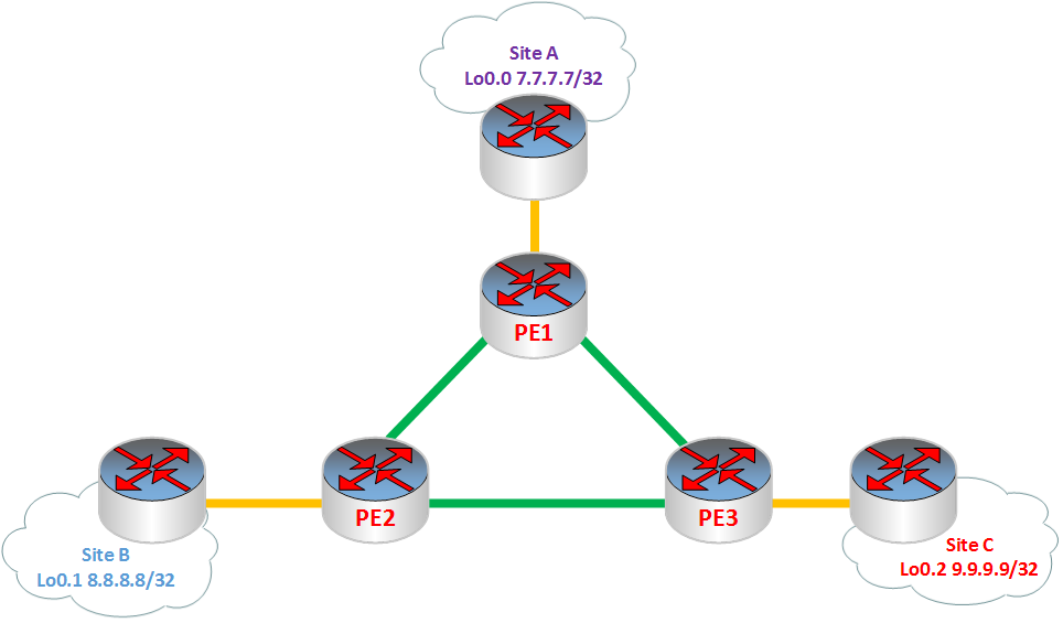
I will be using 1x EX4200 with routing instances to separate the routing tables and 3x SRX220h2 as the Provider Edge (PE) routers. I will have 3 routing instances on the EX4200, each will represent a different Site location and will have a single VPLS instances across the 3x PE routers. As shown below, Logical Topology that will be used for this VPLS lab will be:
To have create a VPLS instance you will need to have the following configured:
- IGP: On all PE routers with traffic-engineering enabled
- MPLS: Label Switched Paths (LSPs) configured between the PE routers
- BGP: BGP configured between the PE routers (BGP enabling VPLS method)
This is my base configuration for my 3 PE routers
Base configuration⌗
PE Router 1⌗
root@Top\_SRX> show configuration
## Last commit: 2015-05-15 15:47:03 UTC by root
version 12.1X44-D45.2;
system {
    host-name Top\_SRX;
    root-authentication {
        encrypted-password "$1$n8lY2iyW$5gx34QuELucAjscTH.vTe1"; ## SECRET-DATA
    }
    services {
        ssh {
            protocol-version v2;
        }
    }
}
interfaces {
    ge-0/0/0 {
        description "Other SRX g0/0/0";
        enable;
        unit 0 {
            family inet {
                address 1.1.1.6/31;
        }
    }
    ge-0/0/1 {
        description "Bottom SRX g0/0/1";
        unit 0 {
            family inet {
                address 1.1.1.4/31;
        }
    }
    ge-0/0/2 {
        description "EX g0/0/2";
    }
    ge-0/0/6 {
        enable;
        unit 0 {
            family inet {
                address 10.1.0.201/24;
            }
        }
    }
    lo0 {
        unit 0 {
            family inet {
                address 1.1.1.1/32;
            }
        }
    }
}
routing-options {
    static {
        route 0.0.0.0/0 {
            next-hop 10.1.0.1;
            no-readvertise;
        }
    }
    autonomous-system 200;
}
protocols {
    lldp {
        interface all;
    }
security {
    forwarding-options {
        family {
            inet6 {
                mode packet-based;
            }
            mpls {
                mode packet-based;
            }
            iso {
                mode packet-based;
            }
        }
    }
}
PE router 2⌗
root@BottomSRX> show configuration
## Last commit: 2015-05-15 15:56:47 UTC by root
version 12.1X44-D45.2;
system {
    host-name BottomSRX;
    root-authentication {
        encrypted-password "$1$8zJP2rqE$aNbSmTjuldkr99uQIp4J30"; ## SECRET-DATA
    }
    services {
        ssh {
            protocol-version v2;
        }
    }
}
interfaces {
    ge-0/0/0 {
        description "Other SRX g0/0/1";
        unit 0 {
            family inet {
                address 1.1.1.9/31;
            }
    }
    ge-0/0/1 {
        description "Top SRX g0/0/1";
        unit 0 {
            family inet {
                address 1.1.1.5/31;
            }
    }
    ge-0/0/2 {
        description "EX g0/0/2";
    }
    ge-0/0/6 {
        enable;
        unit 0 {
            family inet {
                address 10.1.0.202/24;
            }
        }
    }
    lo0 {
        unit 0 {
            family inet {
                address 2.2.2.2/32;
            }
        }
    }
}
routing-options {
    static {
        route 0.0.0.0/0 {
            next-hop 10.1.0.1;
            no-readvertise;
        }
    }
}
protocols {
    lldp {
        interface all;
    }
}
security {
    forwarding-options {
        family {
            inet6 {
                mode packet-based;
            }
            mpls {
                mode packet-based;
            }
            iso {
                mode packet-based;
            }
        }
    }
}
PE router 3⌗
root@Single\_SRX> show configuration
## Last commit: 2015-05-15 16:03:13 UTC by root
version 12.1X44-D45.2;
system {
    host-name Single\_SRX;
    root-authentication {
        encrypted-password "$1$0pm5C2Ie$5ss3qkj8WZxBFU2bTwlyE."; ## SECRET-DATA
    }
    name-server {
        8.8.8.8;
        8.8.4.4;
    }
    services {
        ssh {
            protocol-version v2;
        }
    }
}
interfaces {
    ge-0/0/0 {
        description "Bottom SRX g0/0/0";
        enable;
        unit 0 {
            family inet {
                address 1.1.1.8/31;
        }
    }
    ge-0/0/1 {
        description "Top SRX g0/0/0";
        enable;
        unit 0 {
            family inet {
                address 1.1.1.7/31;
        }
    }
    ge-0/0/2 {
    	description "EX SRX g0/0/2";
    }
    ge-0/0/7 {
        description "Lab Management";
        enable;
        unit 0 {
            family inet {
                address 10.1.0.207/24;
            }
        }
    }
    lo0 {
        unit 0 {
            family inet {
                address 3.3.3.3/32;
            }
        }
    }
}
routing-options {
    static {
        route 0.0.0.0/0 {
            next-hop 10.1.0.1;
            no-readvertise;
        }
    }
    autonomous-system 200;
}
protocols {
    lldp {
        interface all;
    }
}
security {
    forwarding-options {
        family {
            inet6 {
                mode packet-based;
            }
            mpls {
                mode packet-based;
            }
            iso {
                mode packet-based;
            }
        }
    }
}
routing-instances {
    vpls {
        instance-type vpls;
        interface ge-0/0/2.0;
        protocols {
            vpls {
                no-tunnel-services;
                vpls-id 1;
                neighbor 1.1.1.1;
                neighbor 2.2.2.2;
            }
        }
    }
}
This is the configuration I have on the EX4200, which will be used as the 3 different locations. I have enabled OSPF at the each of the sites
EX4200 Configuration⌗
root> show configuration
## Last commit: 2015-03-08 18:33:10 UTC by root
version 12.3R9.4;
system {
    root-authentication {
        encrypted-password "$1$kgkXgKFb$plTKQqiKNknDciGKJ8i8V/"; ## SECRET-DATA
    }
    services {
        ssh {
            protocol-version v2;
        }
    }
}
interfaces {
    ge-0/0/0 {
        description "Top SRX";
        unit 0 {
            family inet {
                address 172.16.1.4/24;
            }
        }
    }
    ge-0/0/1 {
        description "Bottom SRX";
        unit 0 {
            family inet {
                address 172.16.1.2/24;
            }
        }
    }
    ge-0/0/2 {
        description "Other SRX";
        unit 0 {
            family inet {
                address 172.16.1.3/24;
            }
        }
    }
    lo0 {
        unit 0 {
            family inet {
                address 7.7.7.7/32;
            }
        }
        unit 1 {
            family inet {
                address 8.8.8.8/32;
            }
        }
        unit 2 {
            family inet {
                address 9.9.9.9/32;
            }
        }
    }
    me0 {
        unit 0 {
            family inet {
                address 10.1.0.200/24;
            }
        }
    }
}
protocols {
    lldp {
        interface all;
    }
}
routing-instances {
    SiteA {
        instance-type virtual-router;
        interface ge-0/0/0.0;
        interface lo0.0;
        protocols {
            ospf {
                area 0.0.0.0 {
                    interface ge-0/0/0.0;
                    interface lo0.0;
                }
            }
        }
    }
    SiteB {
        instance-type virtual-router;
        interface ge-0/0/1.0;
        interface lo0.1;
        protocols {
            ospf {
                area 0.0.0.0 {
                    interface ge-0/0/1.0;
                    interface lo0.1;
                }
            }
        }
    }
    SiteC {
        instance-type virtual-router;
        interface ge-0/0/2.0;
        interface lo0.2;
        protocols {
            ospf {
                area 0.0.0.0 {
                    interface lo0.2;
                    interface ge-0/0/2.0;
                }
            }
        }
    }
}
LDP⌗
Ill be working off PE1, all the other routers have been configured. Once we have PE1 sorted, we will have a VPLS instance with LDP signaling :)
Firstly, I will configure the interface that is connected the Customer Edge (CE) device, so that the router knows this is apart of the VPLS. We will need to set the encapsulation to VPLS and set the logical interface.
root@Top\_SRX> show configuration interfaces ge-0/0/2
description "EX g0/0/2";
encapsulation ethernet-vpls;
unit 0;
Out of the 3 ways of configuring a VPLS instance using LDP, configuration wise, is the most straightforward. Under the protocols stanza, we will need to make sure all the related protocols are enabled, in addition we will need to make sure the MPLS LSPs correctly configured. It is important to know that, you will only need to set LDP on the loopback address not on any other interfaces that has MPLS configured. This is because the LDP peering with only the other PE and not the interlinks between the routers, this is also why you need to have an IGP configured to get connectivity to the loopback.
protocols {
    rsvp {
        interface ge-0/0/0.0;
        interface ge-0/0/1.0;
        interface lo0.0;
    }
    mpls {
        no-cspf;
        label-switched-path to\_3.3.3.3 {
            from 1.1.1.1;
            to 3.3.3.3;
        }
        label-switched-path to\_2.2.2.2 {
            from 1.1.1.1;
            to 2.2.2.2;
        }
        interface ge-0/0/0.0;
        interface ge-0/0/1.0;
    }
    ospf {
        traffic-engineering;
        area 0.0.0.0 {
            interface ge-0/0/0.0;
            interface ge-0/0/1.0;
            interface lo0.0;
        }
    }
    ldp {
        interface lo0.0;
    }
It is key to remember with all VPNs, their goal is to isolate their routing tables from other networks; this is no different with VPLS. We will need to create an isolated VPLS instance, to allow traffic between Sites A, B and C to be independent from the rest of the network. With this in mind, we will need to configure a Routing-Instance and include statement instance-type vpls
root@Top\_SRX> show configuration routing-instances
vpls {
    instance-type vpls;
    interface ge-0/0/2.0;
    protocols {
        vpls {
            no-tunnel-services;
no-tunnel-servicesneeds to be configured, as device I’m using (SRX220h2) doesn’t have Tunnel Service PIC. This statement creates a label-switched interface (LSI) to provide VPLS functionality. For more information check here
We can see everything is working, when I do a show route we can see that all 3 sites have learnt the loopback address via OSPF
Site A Routing Table⌗
SiteA.inet.0: 6 destinations, 6 routes (6 active, 0 holddown, 0 hidden)
+ = Active Route, - = Last Active, \* = Both

7.7.7.7/32         \*\[Direct/0\] 17:54:17
                    > via lo0.0
8.8.8.8/32         \*\[OSPF/10\] 01:05:51, metric 1
                    > to 172.16.1.2 via ge-0/0/0.0
9.9.9.9/32         \*\[OSPF/10\] 01:05:51, metric 1
                    > to 172.16.1.3 via ge-0/0/0.0
224.0.0.5/32       \*\[OSPF/10\] 17:54:17, metric 1
                      MultiRecv
Site B Routing Table⌗
SiteB.inet.0: 6 destinations, 6 routes (6 active, 0 holddown, 0 hidden)
+ = Active Route, - = Last Active, \* = Both

7.7.7.7/32         \*\[OSPF/10\] 01:05:51, metric 1
                    > to 172.16.1.4 via ge-0/0/1.0
8.8.8.8/32         \*\[Direct/0\] 17:54:17
                    > via lo0.1
9.9.9.9/32         \*\[OSPF/10\] 01:05:56, metric 1
                    > to 172.16.1.3 via ge-0/0/1.0
224.0.0.5/32       \*\[OSPF/10\] 17:54:17, metric 1
                      MultiRecv
Site C Routing Table⌗
SiteC.inet.0: 6 destinations, 6 routes (6 active, 0 holddown, 0 hidden)
+ = Active Route, - = Last Active, \* = Both

7.7.7.7/32         \*\[OSPF/10\] 01:05:51, metric 1
                    > to 172.16.1.4 via ge-0/0/2.0
8.8.8.8/32         \*\[OSPF/10\] 01:05:56, metric 1
                    > to 172.16.1.2 via ge-0/0/2.0
9.9.9.9/32         \*\[Direct/0\] 17:54:17
                    > via lo0.2
224.0.0.5/32       \*\[OSPF/10\] 17:54:17, metric 1
                      MultiRecv
BGP⌗
Time to move onto the BGP version of configuration a VPLS. We will keep the same configuration above keep on the all the PEs. Using BGP configuration for VPLS is extremely useful as if more scalable and if you already have BGP running on your network, you don’t need to create any new BGP sessions for the VPLS session!
Firstly we will need to set the autonomous system (AS) number and have our BGP peering session with the other PEs. Note that we have selected the family l2vpn signaling
[edit]
root@Top\_SRX# show routing-options autonomous-system
200;

[edit]
root@Top\_SRX# show protocols bgp
group PE-routers {
    type internal;
    local-address 1.1.1.1;
    family l2vpn {
        signaling;
    }
    peer-as 200;
    neighbor 2.2.2.2;
    neighbor 3.3.3.3;
}
As similar with L3VPNs, under the VPLS routing-instance, we will need to add Route-Target and Route-Distinguisher. This is because unlike with we used LDP, we don’t have defined neighbor under the VPLS stanza. Additionally under the VPLS protocol site-identifiers have to be added.
The Route-Target and Route-Distinguisher on all the PEs in the VPLS instance have to be same
[edit routing-instances vpls]
root@Top\_SRX# show
instance-type vpls;
interface ge-0/0/2.0;
route-distinguisher 200:100;
vrf-target target:200:100;
protocols {
    vpls {
        no-tunnel-services;
        site SiteC {
            site-identifier 3;
        }
    }
}
We can see everything is working, when I do a show route we can see that all 3 sites have learnt the loopback address via OSPF still :D
Site A Routing Table⌗
SiteA.inet.0: 6 destinations, 6 routes (6 active, 0 holddown, 0 hidden)
+ = Active Route, - = Last Active, \* = Both

8.8.8.8/32         \*\[OSPF/10\] 00:02:11, metric 1
                    > to 172.16.1.2 via ge-0/0/0.0
9.9.9.9/32         \*\[OSPF/10\] 00:02:16, metric 1
                    > to 172.16.1.3 via ge-0/0/0.0
224.0.0.5/32       \*\[OSPF/10\] 22:38:49, metric 1
                      MultiRecv
Site B Routing Table⌗
SiteB.inet.0: 6 destinations, 6 routes (6 active, 0 holddown, 0 hidden)
+ = Active Route, - = Last Active, \* = Both

7.7.7.7/32         \*\[OSPF/10\] 00:02:11, metric 1
                    > to 172.16.1.4 via ge-0/0/1.0
9.9.9.9/32         \*\[OSPF/10\] 00:02:11, metric 1
                    > to 172.16.1.3 via ge-0/0/1.0
224.0.0.5/32       \*\[OSPF/10\] 22:38:49, metric 1
                      MultiRecv
Site C Routing Table⌗
SiteC.inet.0: 6 destinations, 6 routes (6 active, 0 holddown, 0 hidden)
+ = Active Route, - = Last Active, \* = Both

7.7.7.7/32         \*\[OSPF/10\] 00:02:16, metric 1
                    > to 172.16.1.4 via ge-0/0/2.0
8.8.8.8/32         \*\[OSPF/10\] 00:02:11, metric 1
                    > to 172.16.1.2 via ge-0/0/2.0
224.0.0.5/32       \*\[OSPF/10\] 22:38:49, metric 1
                      MultiRecv
LDP & BGP⌗
We are also able to configure a VPLS instance with LDP and BGP. We will use the same configure as above, as we will only need a few changes. We will need to change the family l2vpn stanza in the BGP session from signaling to auto-discovery-only, add l2vpn-id and remove the entire configuration under the protocol vpls (except no-tunnel-services) stanza in VPLS routing instance.
root@Top\_SRX# show protocols bgp
group PE-routers {
    type internal;
    local-address 1.1.1.1;
    family l2vpn {
        auto-discovery-only;
    }
    peer-as 200;
    neighbor 2.2.2.2;
    neighbor 3.3.3.3;
}

root@Top\_SRX# show routing-instances vpls
instance-type vpls;
interface ge-0/0/2.0;
route-distinguisher 200:100;
l2vpn-id l2vpn-id:200:100;
vrf-target target:200:100;
protocols {
    vpls {
        no-tunnel-services;
    }
}
We can see everything is working, when I do a show route protocol ospf we can see that all 3 sites have learnt the loopback address via OSPF still :D
Site A OSPF Routing Table⌗
SiteA.inet.0: 6 destinations, 6 routes (6 active, 0 holddown, 0 hidden)
+ = Active Route, - = Last Active, \* = Both

8.8.8.8/32         \*\[OSPF/10\] 00:00:18, metric 1
                    > to 172.16.1.2 via ge-0/0/0.0
9.9.9.9/32         \*\[OSPF/10\] 00:00:18, metric 1
                    > to 172.16.1.3 via ge-0/0/0.0
224.0.0.5/32       \*\[OSPF/10\] 23:48:35, metric 1
                      MultiRecv
Site B OSPF Routing Table⌗
SiteB.inet.0: 6 destinations, 6 routes (6 active, 0 holddown, 0 hidden)
+ = Active Route, - = Last Active, \* = Both

7.7.7.7/32         \*\[OSPF/10\] 00:00:18, metric 1
                    > to 172.16.1.4 via ge-0/0/1.0
9.9.9.9/32         \*\[OSPF/10\] 00:00:23, metric 1
                    > to 172.16.1.3 via ge-0/0/1.0
224.0.0.5/32       \*\[OSPF/10\] 23:48:35, metric 1
                      MultiRecv
Site C OSPF Routing Table⌗
SiteC.inet.0: 6 destinations, 6 routes (6 active, 0 holddown, 0 hidden)
+ = Active Route, - = Last Active, \* = Both

7.7.7.7/32         \*\[OSPF/10\] 00:00:18, metric 1
                    > to 172.16.1.4 via ge-0/0/2.0
8.8.8.8/32         \*\[OSPF/10\] 00:00:23, metric 1
                    > to 172.16.1.2 via ge-0/0/2.0
224.0.0.5/32       \*\[OSPF/10\] 23:48:35, metric 1
                      MultiRecv
You can get indepth detail about VPLS from Juniper Website here